Patient Care Management System
Instructions:
PATIENT CARE MANAGEMENT SYSTEM
The project requires students to perform three phases: (a) requirements analysis, (b) system and database design, and (c) a project plan. Note that in the phase 3, students are required to use the MS Project software for their project schedule.
The following layout format covering a title page and all three phases is recommended for the project.
Phase 1: Requirement analysis
A. Problem definition
B. Issues
C. Objectives
D. Requirements
E. Constraints
F. Description of the proposed system G. Logical model design
1. Data flow diagrams
- · Context diagram
- · Diagram 0
· Descriptions of processes in each diagram
2. Descriptions of outputs/inputs/performance/security or controls H. Specific requirements, if any (interface, operational, resource, performance, etc.)
Phase 2: System and database design
A. User interface
Design an overall user interface consisting of screens, commands, controls, and features to enable users to use the system.
1.How data will be input to the system?
· The physical layout for each input
· The input design and procedures
2. How data will be output from the system?
· The physical layout for each output
· The output design and procedure
B. Data design Develop a plan for data organization, storage, updating, and retrieval.
- Database design
· Database tables with their attributes should be presented
· Primary key(s) should be identified in each table, if any
· Three steps of normalization should be included.
2. Entity-relationship diagrams
3. Data file storage and access
Solution
Patient Care Management System
1 Introduction
As living standards improve, social values and healthcare needs also become diverse. Medical accidents, increased patient information and poor patient care have increased interest in healthcare. Many researchers want to come up with ways through which healthcare can be easily managed. Technology is the main technique used to in solving problems in health sector. Through technology, patient care activities can easily be managed (Yang & Kim 2013).
This project entails development of patient care management system. It is set to benefit both the public and the medical team. The system will be divided into two main modules – client and administration modules. However, this document only addresses requirement analysis and system design. The remaining sections of the project will therefore address requirement analysis, database and system design and project plan.
2 Requirements analysis
2.2 Problem definition
There are diverse activities involved in patient care. These activities include billing, treatment, and monitoring of patients among others. Manual Management makes coordination of patient care activities stressful. With manual systems, tracking of activities in different departments of a healthcare facility is difficult.
Lack of a proper management system that can be in healthcare has led to many inconveniences. The inconveniences are mainly caused by weaknesses in the old or existing system. They include reliance on manual systems or computer based system with few capabilities. Sharing of information between different organizations and departments is also difficult in manual systems. Some health care organizations have computer based systems but they are still inefficient. Most of these systems are not interactive enough. They are mostly limited to storing patient records, producing receipts, payroll, inventory etc (Ngafeeson 2014). This patient care management system will allow cross-border interaction where both patients and medical practitioners can utilize it.
2.3 Problems associated with the existing system
To ensure the complexities associated with patient care are solved, there has to be some reforms in different areas of health care such as patient billing, patient access to care, physician access to other entities and admission among others.
- Patient billing: A hospital’s billing process is very complex such that it may lead to misunderstandings or breakdowns. This can be attributed to disconnect between different departments of the hospital. For instance, there should be proper communication between the admitting department of a hospital and the billing department to ensure that the bill is correct. Since human beings are prone to errors, they are also bound to make mistakes during billing process. Bills should be produced directly by the system to the patient and the details stored for reference.
- Patient access to care: Changing patient needs and increasing patient expectations have led to increased demand for readily available care. Patients should be in a position to book appointments and easily consult physicians. This can only be provided by a system that allows online booking and monitoring of appointments and consultations.
- Physician access to other entities: The complexities in healthcare require efficient and timely access to different departments of a health facility. If a system is developed that can link all departments of a health facility then medical practitioners can easily carry out their duties. It will also reduce time wastage and errors that arise from manual activities.
- Admission: For easy processing of patient details, a patient should be registered in the system. A good system should therefore allow admissions department to register a patient and allocate identification number.
- Diagnosis: With emergence of strange diseases, it is difficult for doctors to always keep their knowledge up to date. A system that can store a body of knowledge about diseases (including emerging diseases) and be able to produce diagnosis using the symptoms given and the body of knowledge will make treatment easier.
2.4 Objectives
2.4.1 Main objective
The main objective of this project is to create a patient care management system that can effectively serve both patients and medical practitioners to ensure proper patient care in health care facilities.
2.4.2 Specific objectives
- To analyze existing literature on health care systems
- To analyze and identify the weaknesses of the existing health care systems
- To identify patient care management system requirements
- To design and implement an automated patient care management system
- To test and evaluate the patient care management system
2.5 Requirements specification
This section gives an analysis of the requirements of the patient care management system. The requirements are categorized into three – functional, non-functional and systems requirements.
2.5.1 Functional requirements
These are the functions the system is expected to perform.
- Registration: The system shall allow admissions officer to register a patient and allocate personal Identification code.
- Drug prescription: The system shall prescribe drugs to patients from the pharmacy.
- Store records: The system shall facilitate storage of all the information generated such as bill, prescriptions and appointment details into the database.
- Authentication: The system shall be able to authenticate each user that logs into the system using usernames and passwords.
- Assign room: The system shall allocate a patient a room.
- Allocate a bed: The system shall allocate a patient a bed.
- Manage appointments: The system shall allow patients to book and keep track of appointments. Physicians should also approve appointments.
- Generate bills: The system shall be able to generate bills for all the patients.
- Prescription: The system shall be able to produce prescription for the drugs given.
2.5.2 Non-functional requirements
These are attributes that the system or the environment should posses. They include security, reliability, maintainability, performance and usability.
- Security: The system shall be able to authenticate each user that logs in to the system. It shall be able to match the login ID and password provided by the user with the one in the system’s database.
- Reliability: The system shall be reliable. In case of any failure, the data in the system should not get lost because it is backed up.
- Maintainability: The system shall be flexible enough to allow enhancement in its functionality to suit changing requirements.
- Performance: The overall response time of the system on request of information shall not be more than 1 second. The user interface on the other hand should load within 5 seconds.
- Usability: The system shall provide different views for each user depending on the specified activities of a user. Each view shall have necessary information to guide users on their actions. A help link shall also be available to provide guidance in case a user needs help.
2.5.3 System requirements
This section gives a description of the hardware and software components needed for the system to run efficiently.
2.5.3.1 Hardware components
The table below shows the hardware components required for a machine to function properly when using the system.
| Hardware component | System requirement |
| Display | 64bit system, 1024* 768 resolution |
| Memory | 4GB RAM |
| processor | 2.16 GHz Duo core |
| Disk space | 250 GB |
2.5.3.2 Software components
The table below shows the software components needed for the machine to function properly when using the system.
| Software component | System requirement |
| Operating system | Windows 7 or later |
| Run-time environment | Tomcat/apache server |
| Database management system (DBMS) | MySQL |
2.6 Constraints
2.6.1 General constraints
- The system must be developed within the stipulated time.
- The system should be user friendly.
- Every user that logs into the system must be authenticated.
- Every system user must be computer literate.
2.6.2 Design constraints
- The system will make use of MySQL database.
- The system shall run on windows 7 or latter version of operating system.
- The system will be a web based application.
2.7 Logical model of the proposed system
2.7.1 Context diagram
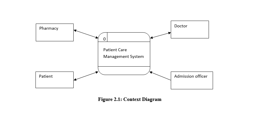
This diagram, also known as level 0 diagram, represents one process (process 0) Data Flow Diagram (DFD). It shows how external entities interact with the system without showing how internal structure of the system looks like. Figure 2.1 shows how the external entities of the patient care health system interact with the system. The main aim of this diagram is to focus on external events and factors that must be considered to ensure the requirements and constraints are fulfilled. The main external entities to this system are pharmacy, doctor, patient and admission officer.

2.7.2 Logical flow of information
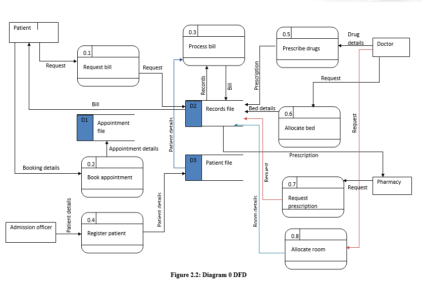
Logical flow of information is represented using Diagram 0 DFD. As the name suggests, DFDs are used to show flow of information in a system and the interaction between different entities of a system. Figure 2.2 shows the main processes of the system and how they interact. Each of the processes in the figure is described below.
- Request Bill: A patient requests for bill. The system sends the request to the records file and retrieves bill for the patient.
- Book appointment: A patient books appointment by entering appointment details into the system. The system stores the details in the appointments files
- Register patient: An admission officer enters patient details and the system stores them in the patient file.
- Process bill: The system uses patient’s details and records to process bill for a patient which is then stored in the records file.
- Prescribe drugs: The system develops prescription from the drugs given and the body of knowledge it contains.
- Allocate room: The system will allocate a patient a room on request by the doctor. The details are then stored in the records file.
- Allocate bed: The system will allocate a patient a bed on request by the doctor and the details Stored in the records file.
- Request prescription: The person in charge of pharmacy will request for a patient’s prescription. The system will retrieve the prescription and display it to him.

3 System and database design
3.2 User interface
3.2.1 Inputs
The interface will contain forms that will be used to capture user details. There will be several views that will allow a user to explore the system.
- Login page: There will be a single login page for all the users in the system. The page will contain userID, password and userType fields. The userType field is used to identify the type of user that is logging in. Form validation will ensure that the data entered in the fields is in the correct format. The request for login will be sent to server to confirm if the login details match the ones in the database.
- Admission officer’s page: An admission officer’s page contains forms with labeled fields where the administrator enters the details of the user being registered. The forms are validated such that the data entered must be in the correct format.
- Doctor’s pages: Doctor’s pages contain forms that are used for capturing drug details for prescription development, and room and bed allocation details. All the forms are validated to ensure that the information send to the server is in the right format.
- Patient’s pages: A patient only has pages for requesting bill and booking appointments. All the forms in the pages are validated to ensure that only correctly formatted content is entered.
- Pharmacy page: An officer in charge of pharmacy only has one page for sending prescription request. All the fields in the forms are validated to ensure data integrity.
3.2.2 Outputs
All the details that have to be presented to the user will be in table format. The server will receive request, process it and then format the result into the required format for display to the user. In this case, all the results will be in table format that is printable incase needed. To print the result, it will be converted in pdf format. In case a user tries to login with the wrong details, the login page is re-displayed with a warning message.
3.3 Data design
3.3.1 Database design
This section contains the different entities (tables) of the database, there attributes and data types.
Table 1: patient
| Field name | Data type | Description | Field size | constraint |
| Name | Varchar | The name of the patient | 30 | |
| Patient_ID | varchar | The ID of the patient | 10 | Primary key |
| Password | varchar | The password of the patent | 20 | |
| Date of birth | Date/time | The date of birth of the patient | 20 | |
| gender | varchar | The gender of the patient | 10 | |
| Marital_status | varchar | Marital status of the patient | 20 |
The table above shows the structure of the patient details table.
Table 2: officer
| Field name | Data type | Description | Field size | constraint |
| Name | varchar | The name of the admissions officer | 30 | |
| Officer_ID | varchar | The ID of the admissions officer | 10 | Primary key |
| Password | varchar | The password of the admissions officer | 20 |
The above table shows the structure of admissions officer details table
Table 3: pharmacy officer
| Field name | Data type | Description | Field size | constraint |
| Name | varchar | The name of the pharmacy officer | 30 | |
| Admin_ID | varchar | The ID of the pharmacy officer | 10 | Primary key |
| Password | varchar | The password of the pharmacy officer | 20 |
The above table shows the structure of pharmacy officer details table.
Table 4: doctor
| Field name | Data type | Description | Field size | constraint |
| Name | varchar | The name of the medical practitioner | 30 | |
| Med_ID | varchar | The ID of the medical practitioner | 10 | Primary key |
| Password | varchar | The password of the medical practitioner | 20 |
The above table shows the structure of doctor details table
Table 5: records
| Field name | Data type | Description | Field size | constraint |
| Record_ID | varchar | The ID of the record | 10 | Primary key |
| Patient_ID | varchar | The ID of the patient | 10 | Foreign key |
| Drugs | varchar | The drugs administered to the patient | 50 | |
| Bill-id | int | The ID of the bill incurred | 20 | Foreign key |
| Room_id | varchar | The room number of the patient | 10 | Foreign key |
| Bed_id | varchar | The ID of the bed of the patient | 10 | Foreign key |
| Med_ID | varchar | The ID of the doctor that attended to the patient | 10 | Foreign key |
| Category | varchar | The category of the patient (in-patient/out-patient) | 20 | |
| Period | Date/time | The period of admission | 30 |
The above table shows the structure of medical records table.
Table 6: bills
| Field name | Data type | Description | Field size | constraint |
| Bill_id | varchar | The ID of the bill | 10 | Primary key |
| Patient_id | varchar | The ID of the patient | 10 | Foreign key |
| bill | varchar | The bill | 20 | |
| Status | varchar | The status of the bill (i.e paid/not paid) | 20 |
The table above shows the structure of bills table
Table 7: beds
| Field name | Data type | Description | Field size | constraint |
| Bed_ID | varchar | The ID of the bed | 10 | Primary key |
| Room_ID | varchar | The ID of the room | 10 | Foreign key |
| Bed_Number | varchar | The bed number | 20 | |
| Status | varchar | The status of the bed (occupied/not occupied) | 20 |
The table above shows the structure of beds table.
Table 8: rooms
| Field name | Data type | Description | Field size | constraint |
| Room_id | varchar | The Id of the room | 10 | Primary key |
| Room_number | varchar | The number of the room | 20 | |
| Number_of_Beds | varchar | The number of beds in the room | 20 | |
| Occupied_beds | varchar | The occupied beds in the room | 20 |
The table above shows the structure of room’s table.
Table 9: appointments
| Field name | Data type | Description | Field size | constraint |
| Appointment_ID | varchar | The ID of the appointment | 10 | Primary key |
| Med_ID | Varchar | The ID of the Medical practitioner in the appointment | 10 | Foreign key |
| Patient_ID | Varchar | The ID of the patient in the appointment | 10 | Foreign key |
| Date | Date/time | The date of the appointment | 20 | |
| Time | Date/time | The time of the appointment | 10 | |
| Approval_status | varchar | Approval status of the appointment | 20 | |
| Fulfillment_status | varchar | The status of the appointment | 20 |
The above table shows the structure of the appointment table.
3.3.2 Entity relationship diagrams
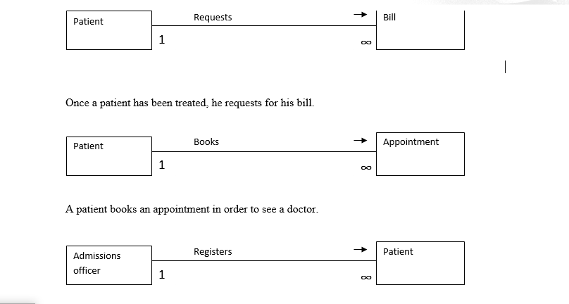
The diagrams below show the relationships between different entities of the database. Through the diagrams, the relationships between the tables are created.


Pharmacy officer administers drugs to patients.
3.4 System architecture
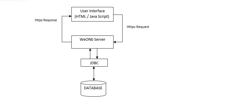
This section presents the architecture of the overall system. Since it is a wed-based system the architecture is divided into three layers – database, interface and server layers as shown in the figure below.

4 Project plan and schedule
This section presents the activities involved in the development and implementation of the system. Each of the activities, there costs and duration are documented.
Project activities and tasks
| Activity | Cost ($) |
| System planning | 25000 |
| System analysis | 250000 |
| System design | 200000 |
| Implementation | 150000 |
| Testing and evaluation | 260000 |
| System deployment | 500000 |
| Total costs | 1385000 |
Project schedule
| Activities | Months | |||||||||||
| 1 | 2 | 3 | 4 | 5 | 6 | 7 | 8 | 9 | 10 | 11 | 12 | |
| System planning | ||||||||||||
| System analysis | ||||||||||||
| System design | ||||||||||||
| Implementation | ||||||||||||
| Testing and evaluation | ||||||||||||
| Deployment |
5 Conclusion
This document presents system
analysis for patient care management system. The document contains three
sections – requirement analysis, system design and project schedule.
Reference
Yang, Y & Kim, M. (2013). Analysis of user requirement on U-Healthcare system. International Journal of Business Tourism and Applied Sciences, 1(2), 1 – 10.
Ngafeeson, M. (2014) Healthcare Information Systems: Opportunities and Challenges. Book ections/Chapters. Paper 14.

